Mechatronic - Binnacle

Binnacle of the Mechatronic subject.
Published on September 27, 2024 by vbarcena2020(abito2)
Mechatronic - Binnacle post Mecatronica Binnacle Python C++ Arduino Inkscape Githuh MD / Markdown VSCode Croquis FreeCAD
10 min READ
This post will show you how I progress in the subject “Mecatronica” learning new habilities and programs to do different things as 2D design:
L1 and L2 Learning VSCode and Github
In this labs we learn how to used the basics comands of github to update all our content to the github repositories. Also we learn how to do that in VSCode in a graphic form. I will use the terminal to update the code because I found it more simple due to I get used to it all these years. The mor important comands are:
To clone in local the repository:
$ git clone [url of the repository]
To know the local status of the git repository:
$ git status
To add the new files, or the changes done in the other files:
$ git add [files names]
To add a comment and commit the changes done:
$ git commit -m 'comentario'
To push the changes to the online repository:
$ git push
To pull the changes form the online repository:
$ git pull
To merge the changes or two branches use:
$ git merge [branches]
To create a new branch:
$ git branch [name of the new branch]
To change between branches:
$ git checkout [name of the branch]
To create and change to the new branch:
$ git checkout -b [name of the new branch]
These are the basics commands I used.
Learning Inksacape 2D Design
Fristly, I download the Inkscape program.
The firsts steps whit this program was to learn how to use the program creating this simples designs.


Then after learning how to use the program and design some things in 2D I try to create a simple design of the Proyect we are going to create “Proyecto Mano de Zeus”.
The design is the following:

Learning FreeCAD 3D Design
After learning how to create a simple model of the hand in Inksacape in 2D I try to create a simple structure of all the pieces of which the hand that we want to design and create is composed of. The
The structure is in the following link: Mano.FCStd

Regarding the rest of the 3D design, we used Ultimaker Cura to design the parts based on the original project from which we drew inspiration. We modified the (.lts) component files by applying different values to achieve the best print quality on our 3D printers.
Also I have added a wrist and arm, connect all the blocks and create a plane.

However, this 3D model was a simplification of the real model we aimed to create and was quite far from the complexity of the actual model we used. Therefore, I set out to simulate a more realistic version of the printed model by using its dimensions to create a simpler 3D model that everyone can use and modify as needed.
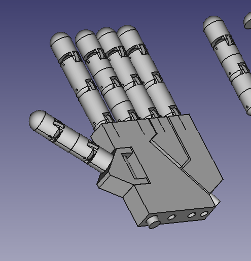
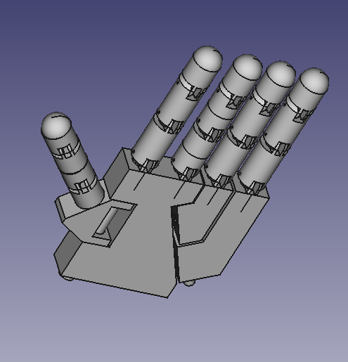
I created this model in FreeCAD using the “Part” tool for general 3D design and “TechDraw” tool for drafting the plan and extracting measurements.
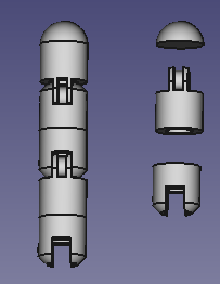
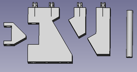
Here are images of the model I developed, which is more similar to the actual one and only covers the hand section, including slots for threading to move the fingers. The wrist and forearm are not designed.
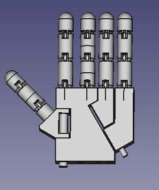
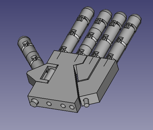
This is a video of the final design.
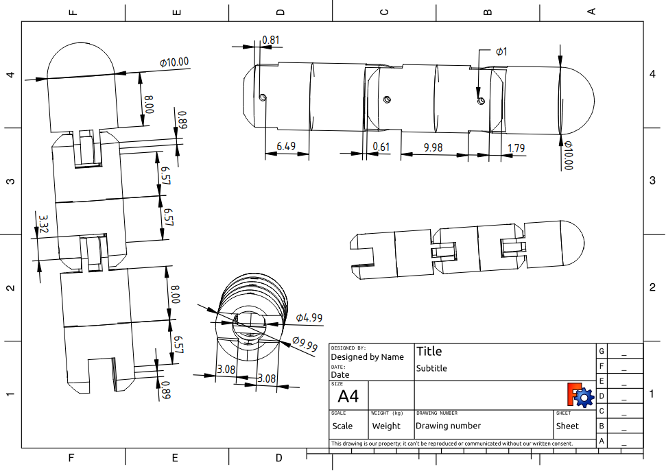
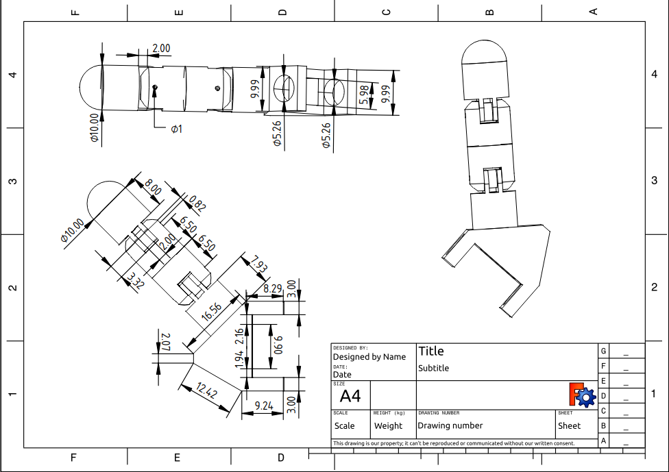
The plans drawn are the following
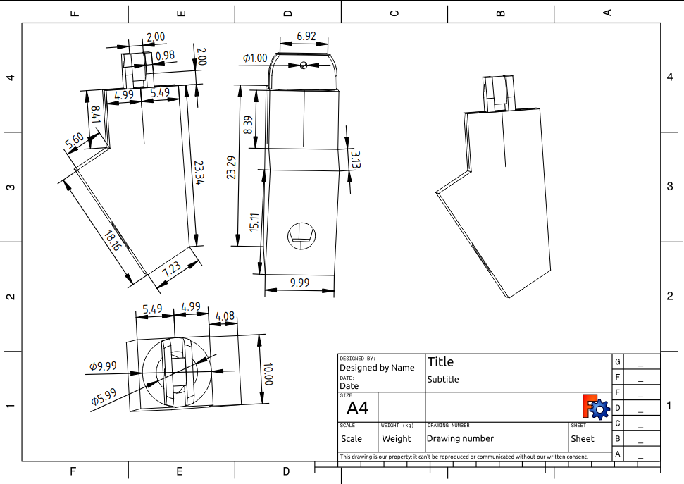
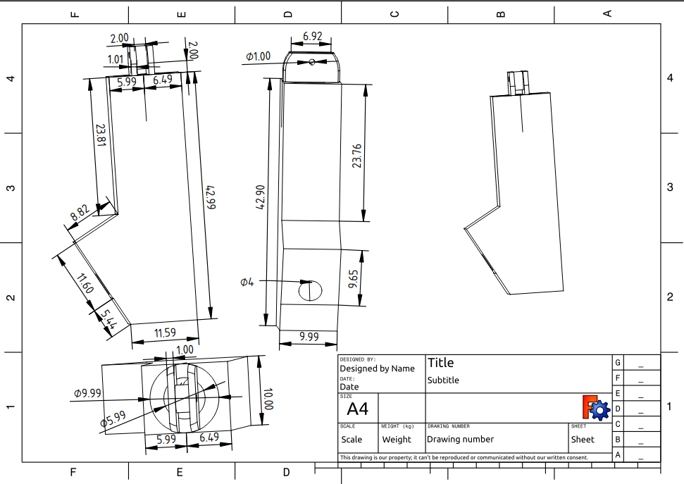
- Finger:

- Thumb:

- Palm:
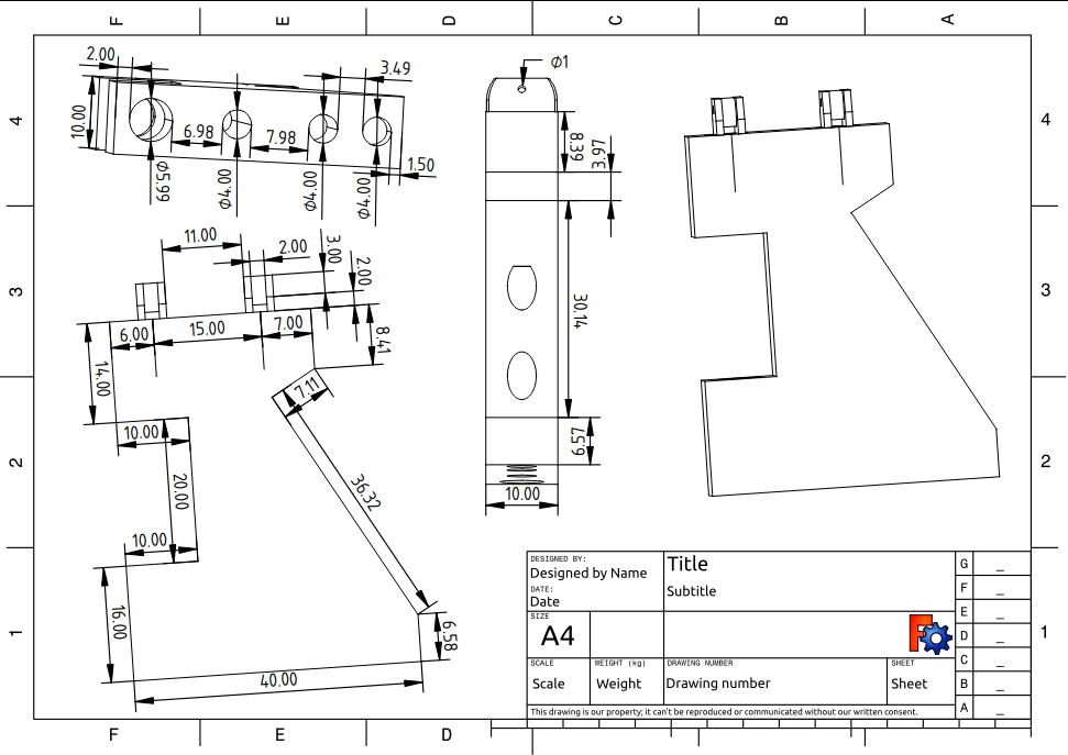

- Ring palm:

- Pinky palm:

- All parts:

And the file with all the 3d design you can find it in hand.FCStd.
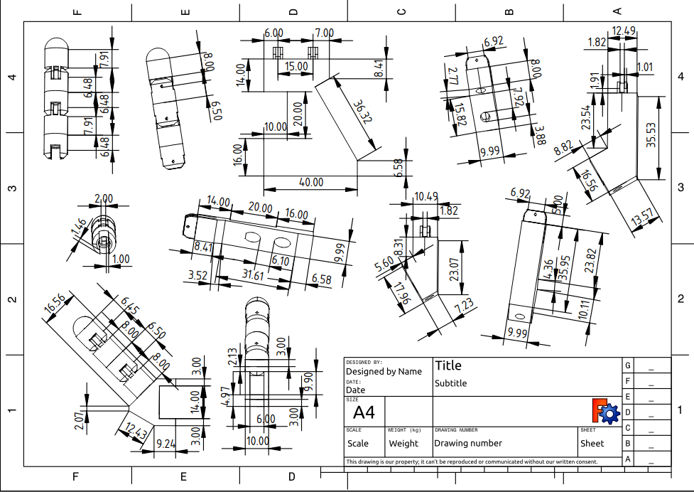
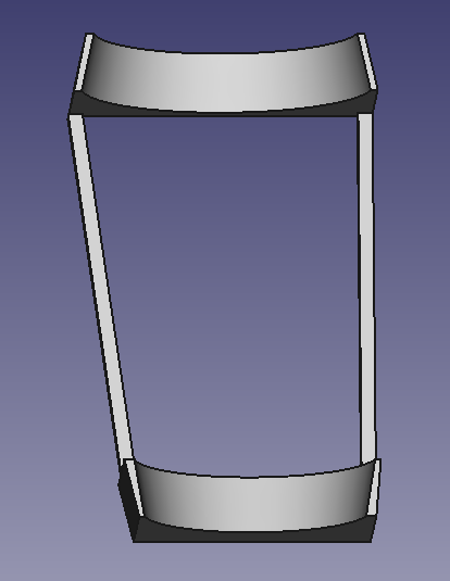
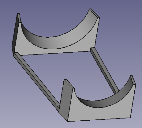
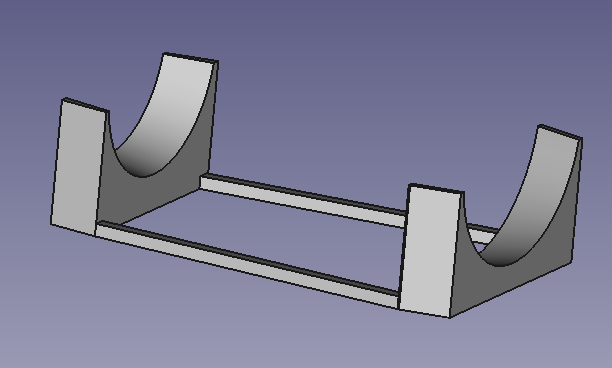
Also I have design an arm support in FreeCAD to support all the arm and hand. The 3D design is the following.
The plan drawn is the following
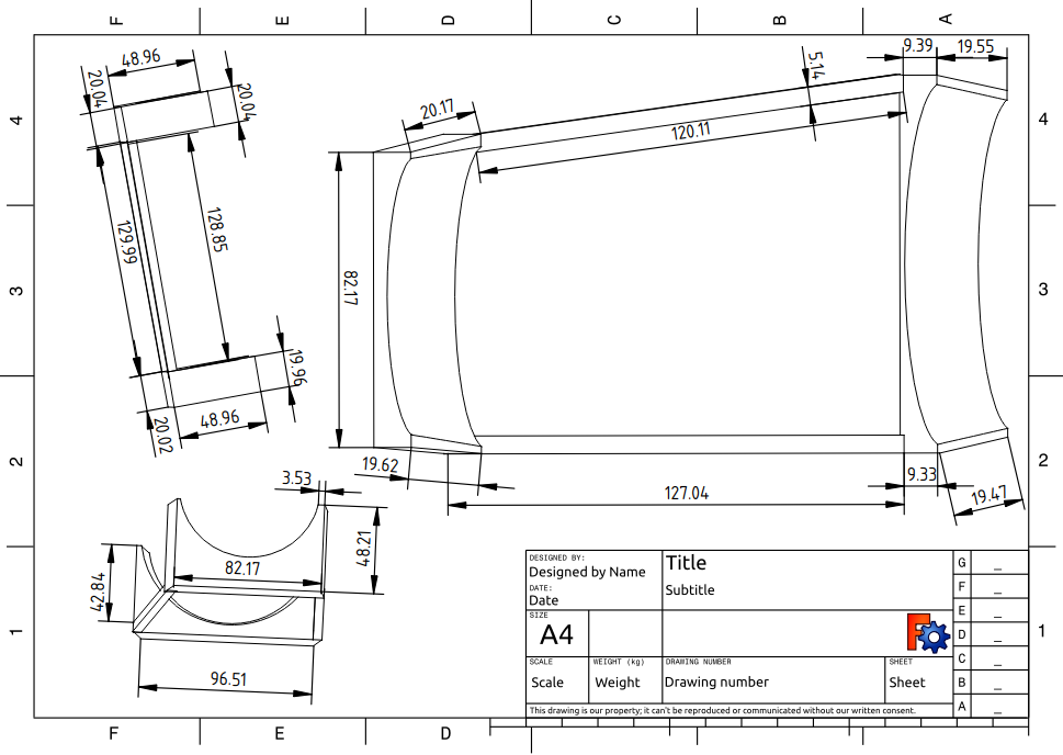

And the file with all the 3d design you can find it in support.FCStd.
Making Electronic Design
To create and design the electronic circuit, fristly, we have to decide which components we are going to need and use.
For the control of the hardware we are going to use an Arduino UNO which can be replace by an Arduino Mega if we want to add more components.

The rest of components are six servos per hand, one for each finger and other for the wrist. This 360 servos model we are going to use are the tower pro mg996r.

Also we have to use a battery to suply the servos with the energy needed.

And to connect all the components we use cables and a protoboard.
To visualize the design I use Fritzing and app which allow us create electronic designs, and this is our:

After trying the code with this connection the servos move to slow or doesn’t have the strong to move the fingers. This happend because the 5V that gives the arduino to the servos is not enough to move the fingers so to fix it I am gonna add a battery to provaid Voltage to the servos.
So the new design is the following:

Zeus Hand Code
The hand code is developed in three languages: C++, Arduino, and Python.
Installation
To ensure the program works correctly, it is necessary to install some libraries beforehand, in addition to the languages used.
Libraries used:
| Library | Terminal Command | Utility |
|---|---|---|
| numpy | pip install numpy | Create and use vectors |
| tkinter | pip install tkinter | Create an interactive interface |
| mediapipe | pip install mediapipe | Detect bodies, arms, and hands |
| pillow | pip install pillow | Process images |
Regarding the development of the hand code, we divided it into several parts:
Movement
The first part focuses on hand movement. Here, we only concentrated on producing the movement of the fingers and wrist using servomotors. This part is programmed in Arduino and C++.
To start, we tried to understand how our servos worked. They move by receiving a value from 0 to 180, which represent speeds. The value 90 indicates zero speed; above this, the servo rotates counterclockwise, and below, it rotates clockwise.
To test the correct operation of the servos, we used a simple code that rotates the servos in both directions alternately.
#include <Servo.h>

Servo myservo;
int currentPos = 0;
int targetPos = 90;
int speedLeft = 80;
int speedRight = 100;
int stopSpeed = 90;

void setup() {
  myservo.attach(3);
  myservo.write(stopSpeed);
  delay(1000);
}

void loop() {
  targetPos = 180;
  moveServoTo(targetPos);

  targetPos = 0;
  moveServoTo(targetPos);
}

void moveServoTo(int targetPos) {
  if (targetPos > currentPos) {
    myservo.write(speedRight);
  } else if (targetPos < currentPos) {
    myservo.write(speedLeft);
  }
  delay(2000);
  myservo.write(stopSpeed);
  currentPos = targetPos;
}
Next, we created a code that moves the servos to specific angles, estimating the time it takes to move from one angle to another. This code only requires the target angle, and it moves the servo as needed to reach that position.
The complete code can be found in ServoM.cpp and ServoM.h.
Communication
After developing the servo movement code, we questioned the best way to command the movements. Several ideas came to mind.
The first was to use an ESP32 and communicate with it via WiFi from the computer. However, we discarded this idea initially since we didn’t have an ESP32 and didn’t want to complicate the code with complex communication. Additionally, achieving the desired reactivity would have been challenging. However, using an ESP32 and WiFi is an idea for the final prototype.
The second was serial communication. This is the method we decided to use because it is straightforward to program and provides very high reactivity. The only drawback is that the Arduino must be connected to the computer, but for now, having the Arduino accessible is not an issue.
Our communication is programmed in Arduino, and the program is responsible for receiving the angles from the detection module and passing them to the movement module.
The complete code is in ServoM.ino.
Detection
After achieving good performance for servo movement and communication, we considered how to detect and determine the angles to pass to the servos.
The first idea was to write the angles using a keyboard. This was the simplest option but a bit slow, as we had to manually input the angles constantly for each servo. Therefore, we discarded it immediately.
The next idea was to develop sliders for all the servos and send the respective values instead of writing them. This method was simple and faster. However, although it wasn’t convenient or quick enough for the project’s goal, we kept it as a testing tool in a separate mode.

Finally, after much thought, we came up with an idea inspired by a course we took called Computer Vision: using a camera to capture an image of our arms and, from that image, calculating the finger angles. This approach provided constant and fast detection. The only drawback was that it was more complex to develop, but we eventually succeeded.


The detection is fully programmed in Python and runs on the computer or device connected to the Arduino via Serial.
The complete code is in mano_zeus.py.
Interface
Finally, we developed a simple interface for users to interact with the program. This allows them to choose the mode and parameters to display while observing real-time detection and the angles passed to the Arduino.
This part is also developed in Python, and here is an image of the developed interface:

The complete code is in mano_zeus.py.